Line Array Bench Test and Gain Setting
RCF is a production partner on an outdoor rock show I’m running this weekend. They sent along 12 of their HDL6-A line array cabinets along with four SUB 8004-AS subwoofers. It’s a killer little rig that packs a punch, with some smart engineering – stay tuned to next month’s issue of Live Sound International for much more on that.
Here, we’re going to focus on getting the cabinets show-ready, which includes two main tasks: checking the boxes on the bench to make sure they’re all working properly, and setting the amplifier input gains to maximize system headroom.
Getting an accurate response measurement of a loudspeaker can be surprisingly challenging, especially in the small reflective room I was working in. Instead, we can use a comparative measurement. By measuring each box and overlaying the traces, we can spot “which one of these things is not like the others,” and thus determine if anything was DOA or damaged in shipping.
For more on this approach, check out this Pat Brown article on ProSoundWeb.
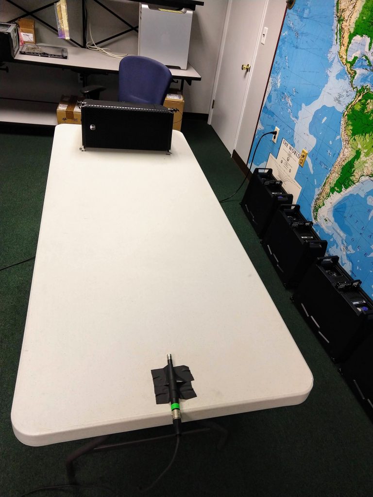
I set up an 8-foot plastic table in the workspace to serve as my “ground plane,” with the box at one end and a measurement mic at the other, taped in place with the tip flush against the table top.
As you might expect, the response of this measurement is not too pretty:
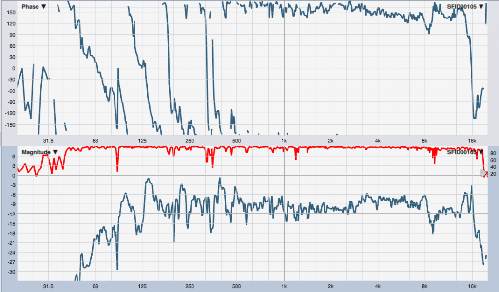
(Note to regular readers: the window layout here has phase on top and magnitude on the bottom – the Smaart default, and the opposite of what you’re used to seeing on this blog.)
This trace shouldn’t be used to make any judgement about frequency response. By substituting the boxes one by one into the same position, we can see how closely they match, which will illustrate any blown drivers or other shenanigans. Here’s all twelve boxes overlaid:
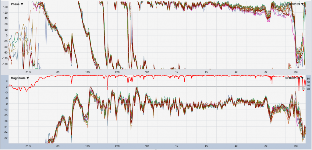
The magnitude traces match well within a dB for most of the range, which is a good sign. The slight deviations in phase response at HF are mostly due to the box not being in exactly the same spot each time. However, notice that all the traces hang around 180° above about 250 Hz.
A good guess here would be a mis-wired mic cable in the measurement rig, or a Pin-3 hot measurement mic (they exist…). This is why it’s a good idea to verify the test rig before you start measuring. In this case that means taking the loudspeaker and the microphone out of the measurement loop and connecting the drive signal cable directly into the mic cable and back into the interface, checking that it’s indeed a flat line at 0 dB and 0°. Swap in a known-good microphone, and we can now confidently state that the polarity inversion we’re seeing is in the box itself.
These loudspeakers use FIR filtering to flatten the phase response through most of the audible spectrum. My guess is that the polarity inversion is RCF’s little trick to allow the FIR portion of the response to meet nicely with the phase response at LF without adding more FIR-induced latency. I’ve written to them to ask, so it will be interesting to see their response. (A polarity inversion isn’t a problem, as long as we know it’s there. That’s why we measure!)
The other task before us was to set the input gains of each box’s amp. We want to make sure all the boxes are playing at the same level given a certain input signal, and also that the system headroom is optimized. If the amps are cranked up too high, the rig will clip prematurely. If they’re too low, we’ve got headroom that we can never use. Ideally, the rig will clip around the same level as the mixing console. If everything clips at once, we’re not bottlenecking our system’s gain structure anywhere.
I have a well-justified fear of playing full-scale sine waves through loudspeakers (especially loudspeakers that do not belong to me!), and a sine wave with its 3 dB crest factor is not very representative of the music signals the box will be reproducing in typical use. Pink noise (crest factor ~ 12 dB) is much closer, so that’s what we’ll use.
I used the console’s onboard oscillator to produce a pink noise signal and raised the level until it was just shy of clipping the desk’s output. The peaks were tickling around -1 dBFS on the meters.
I put the first box on the bench, raised the level until the limiter LED came on, and then backed it off a touch. Yer gonna want earplugs for this. (There’s a little can of worms here – Christopher Grimshaw explains – but it’s a solid starting point, at the very least.)
Then, subsequent boxes followed, finding the “just-not-clipping” point and making sure via the analyzer that the output levels matched the previous boxes. The result is the stack of traces I showed above.
After going through this process, we can go ahead and hang the rig, knowing that it’s behaving properly and we’re getting as much gain out of the system as possible without driving it into limiting or blowing anything up.