Beyond Coverage Angle
When choosing a loudspeaker or designing a loudspeaker array that will produce appropriate coverage for a given audience geometry, a few key parameters guide the way. The first – and most widely recognized – is vertical coverage angle. This determination is simple – from the loudspeaker’s position and perspective, what is the angle inscribed by the coverage area? In other words, how many degrees of coverage do we need to get from the most distant listener to the closest?
Figure 1 shows a generic arena side profile (“section view”). We can see that the amount of vertical coverage required depends on which seating sections are to be sold for the performance.
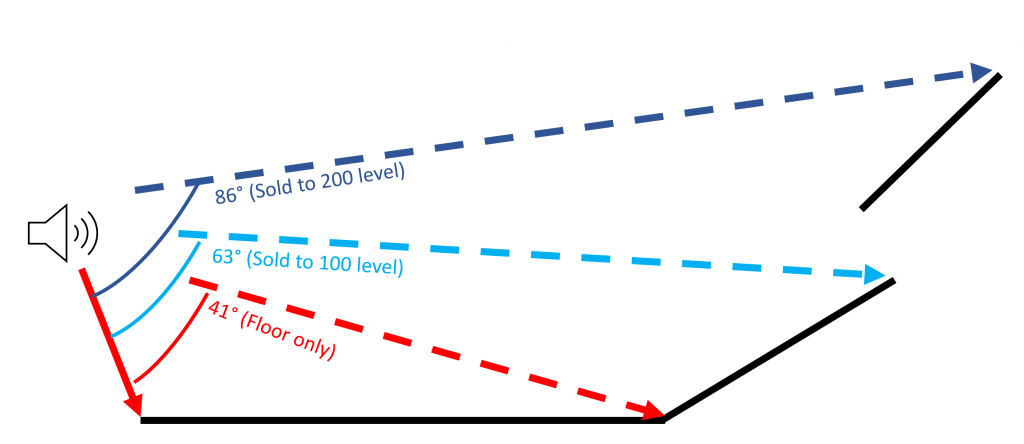
Now it might seem that as long as we have the proper vertical coverage angle, we’re all set for uniform coverage. Not so fast! Knowing how much total coverage we need is a good start, but that’s not all the information we need for uniformity.
Range Ratio
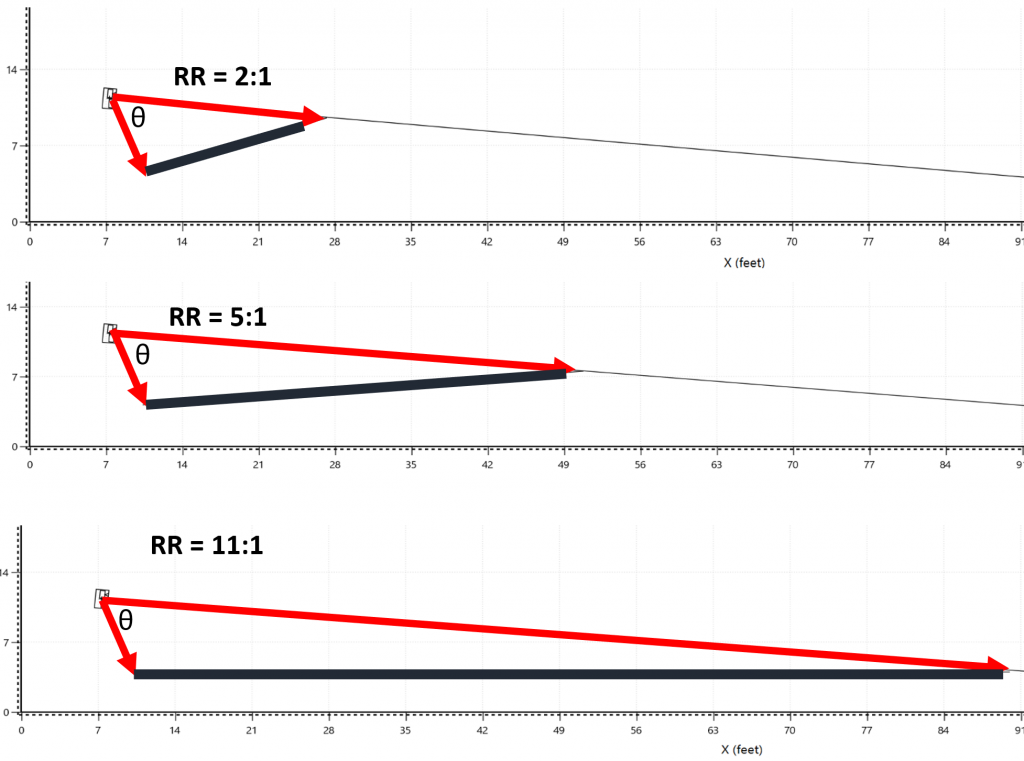
The next parameter to consider is Range Ratio. Range ratio describes the distance from the source to the furthest seat, compared to the distance from the source to the nearest seat. This helps us determine how asymmetrical we need our coverage to be. A low range ratio (like 2:1) means that the furthest listener is only twice as far away as the nearest. We need twice as much SPL (6 dB) to go towards the back if we want to create uniformity. With a larger range ratio like 6:1 (15 dB) we need to design an array that has a lot more output towards the top than at the bottom in order to achieve uniformity from front to back.
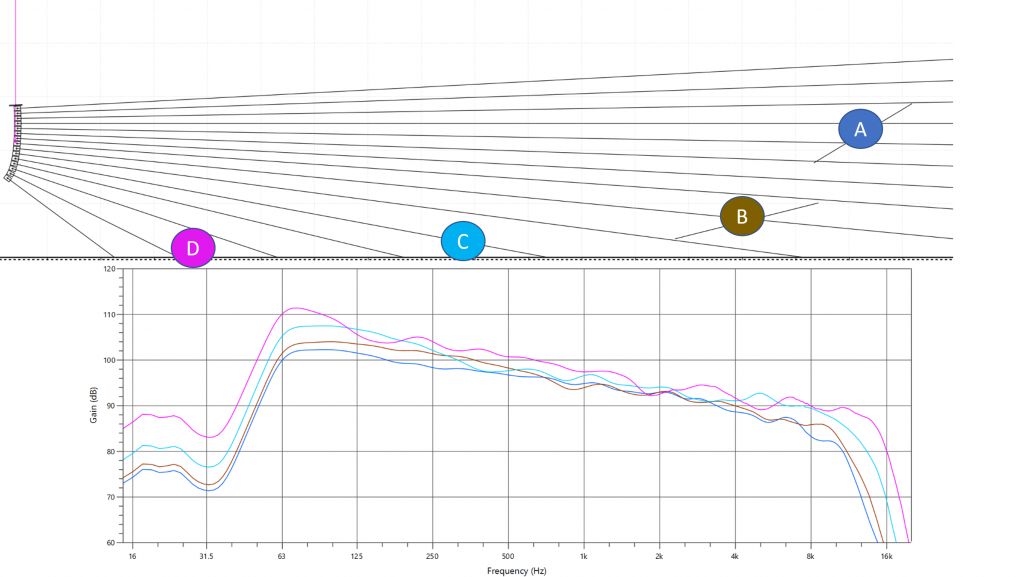
Figure 2 shows the geometry of three difference audience areas with range ratios from 2:1 (6 dB) to 11:1 (21 dB). Despite the fact that all three have the same exact vertical coverage angle, they have drastically different needs for SPL distribution if our goal is to achieve coverage uniformity – the deepest audience area would require an array that has 15 dB more output towards the top than the shallowest audience area.
In order to create asymmetrical dispersion of high frequencies within a given coverage angle, we can manipulate the splay angles between the elements in an array. Smaller inter-element splays mean more elements radiating into the same angular space, and thus more energy headed in that direction. For example, we could achieve 12° of coverage with a single 12° source, two elements at 6°, three elements at 4°, four elements at 3°, six elements at 2°, or 12 elements at 1°. In all cases we will be able to supply the required 12 degrees of vertical coverage, but SPL increases as the splays decrease and the element density increases.
Setting Splay Angles
Now we can tailor the allocation of elements within the array as necessary: the more distant sections of audience geometry will be covered by more elements at smaller splays, while the closer audience sections can be covered by fewer elements at larger splays. As a geometric shorthand for this, we can simply adjust the splay angles until the center lines impact the audience area at equally spaced intervals.
This will get us to a point where we should need only minimal electronic processing (high frequency shading) to achieve uniformity from front to back.
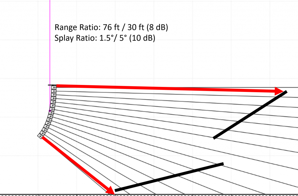
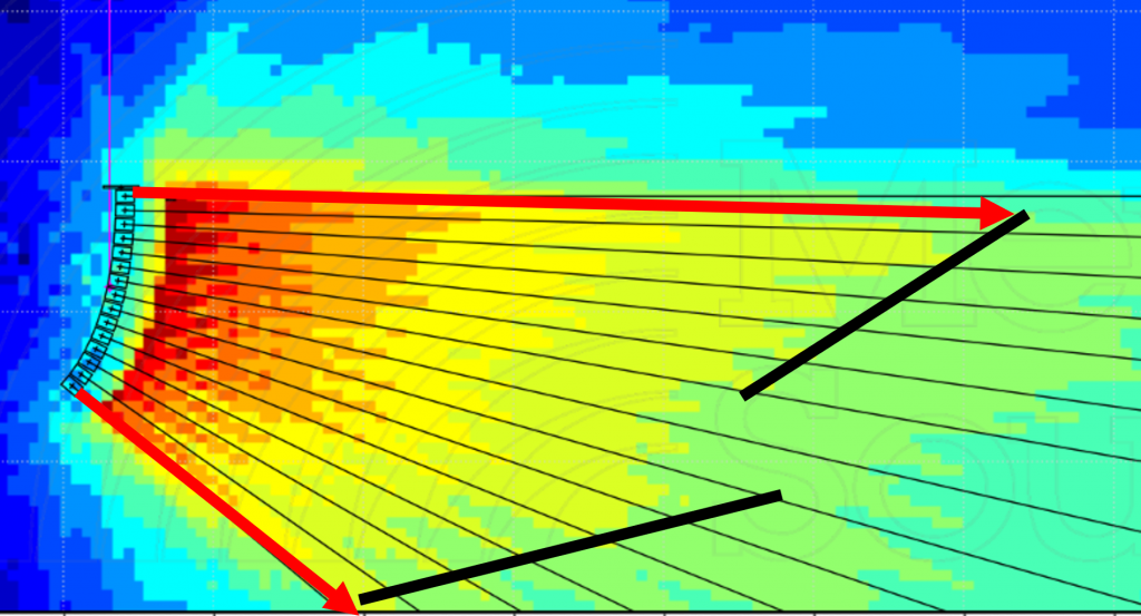
In Figure 3, splay angles have been adjusted to create evenly spaced centerline impacts from back to front (this is how auto-splay algorithms work). This dictates the inter-element splays and overall array curvature, with smaller splays towards the top and wider splays towards the bottom. Since the range ratio is relatively gentle (about 2.5:1, or 8 dB), so is the resulting curvature. Figure 4 shows us that we have indeed created quite uniform HF coverage (4 kHz, 1 octave). The prediction is colored in 3 dB increments, and indicates that all the listeners are now within +/- 1.5 dB at 4 kHz.
Going Long
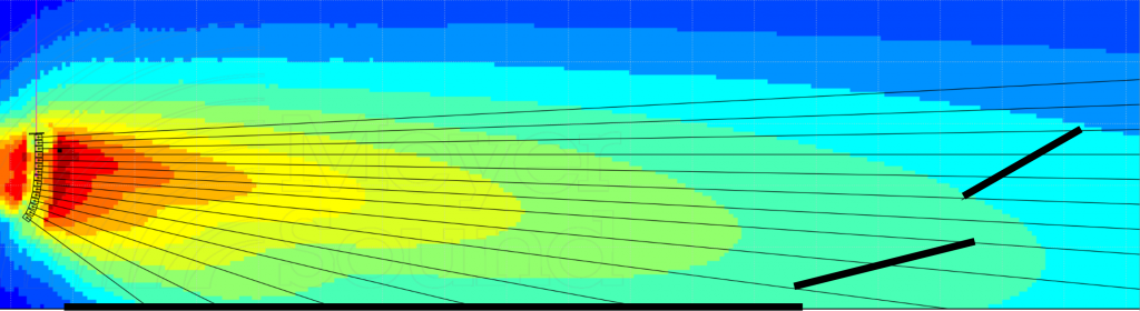
Now let’s push the stage further back into the venue so we can sell more seats. The vertical coverage needs have not changed, but the range ratio has been drastically increased. If we use the same splays / curvature, our energy distribution is now a poor match for the audience geometry, with a 4 color (12 dB) drop from front to back. (Figure 5).
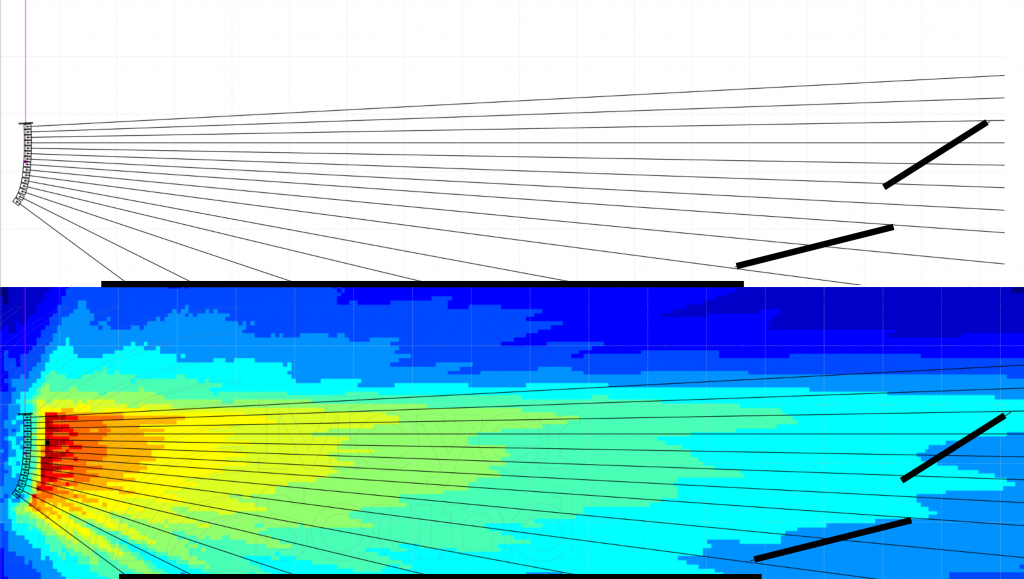
Let’s readjust the splay angles – closing up towards the top, and opening up more towards the bottom, and redistribute the splay within the same total vertical coverage. Now our splays run from 1° to 10° (20 dB) which is a ratio of 1:10 compared to the 3.3 we had with the shallower audience area. Figure 6 shows we’re headed in the right direction again. 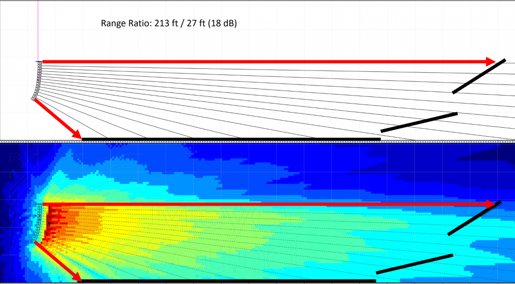
FIGURE 6 – Same vertical coverage area, different splays to fit a different range ratio.
Overshoot
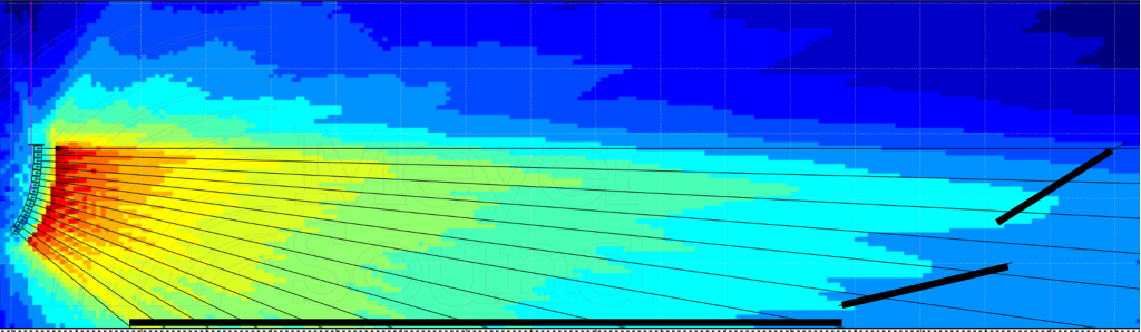
Now we have a new problem: our narrower splays at the top of the array are putting a harder edge on the HF coverage, and we’re missing the last few rows.
We need to tip the entire array up a few degrees and “overshoot” a few boxes to keep them within the coverage. Tipping up by 3 degrees puts our third box on axis with the last row of seats (2 boxes of overshoot) and brings those seats back into coverage.
Now we are mechanically optimized for HF uniformity and a small amount of HF shading on the bottom few boxes will bring us over the finish line.
Line Length and LF
We have one final consideration: so far we have been looking exclusively at HF behavior, where the splay angles are the majority shareholder in coverage behavior. Our coverage at low frequencies is determined by line length. At 250 Hz, we see this array length is a reasonably good fit for the coverage shape we are trying to create (Figure 8).
If it were too wide, we could narrow it by making the line longer (more boxes), which would also mean closing up splay angles to keep the proper overall vertical coverage angle at HF. If it were too narrow, we could shorten the line by taking a few boxes off, and open up splays to restore the proper HF vertical coverage.
In this case we have very good uniformity (+/- 1.5 dB) except for the 200 section which is 3 dB down. If our goal is to preserve tonality (minimize spectral variance) we can easily adjust the HF shading on the top few elements to maintain the overall tonality at a lower level.
The Pudding
Figure 9 shows the final results – consistent tonality from front to back with a controlled level variance (about +/- 3 dB) despite a formidable 18 dB range ratio. This is accomplished predominately mechanically, by properly specifying total vertical coverage, interelement angles / curvature and line length. The only processing used was HF shading (shelving filter) on the top 4 and bottom 3 elements.
Design Parameters
To achieve optimal coverage, line length, overall vertical splay, and inter-element splays / curvature must be able to be manipulated independently. Simply deploying an array with the proper vertical coverage angle does not mean it is an appropriate fit to create uniformity in the audience geometry. We must also consider range ratio (and therefore splay ratio) and line length. Systems which inexorably tie two or more of those design parameters together inherently create design compromises.
Constant curvature systems, for example, bind vertical coverage, interelement splay and line length all together. If the audience plane has a low range ratio – that is, all the listeners are about the same distance from the source – a constant curvature may give satisfactory result at HF. However, the total required vertical coverage angle must then dictate the number of elements, since splay angle is fixed, which by extension means that we lose control of line length as a design parameter, and we must simply accept the LF coverage shape as-is. There is no way to improve LF directivity by increasing line length without increasing vertical coverage angle at the same time, resulting in improper coverage for the application.